|
System
for Monitoring Weather Satellites:
FM Receiver For 134 - 141MHz
(A double conversion
superhetrodyne with pll)

[
BACK ]
IT'S EASY TO
CAPTURE REALTIME IMAGES LIKE THIS DIRECTLY FROM SPACE ON YOUR
PC!
Miroslav
Gola OK2UGS http://www.emgo.cz/

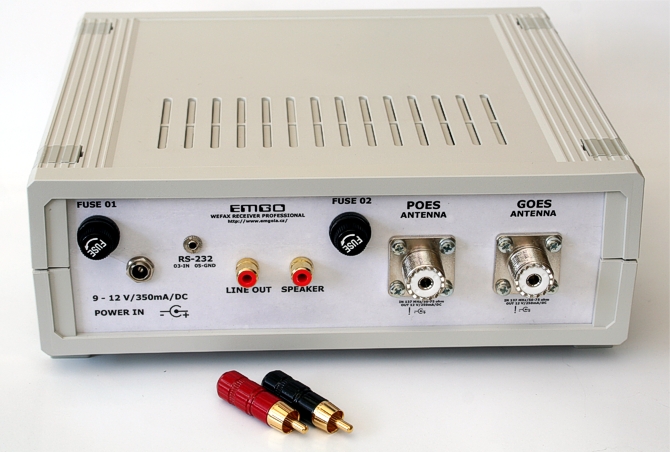
| [02.03.2010] |
|
Introduction
Receiving information from FM meteorological satellites has become an
interesting hobby for thousands of radio enthusiasts all over the
world. Those of you who have already tried internet searches using
such keywords as
NOAA, METEOSAT, 137.5MHz, WEFAX, Meteor etc., will
undoubtedly confirm that they have found hundreds of links to pages of
receiver manufacturers, re-sel-lers, professional users and
particularly ham enthusiasts.

Not long ago history...
It is worth noting that on 1st April 2010 we commemorated the
50th
anniversary of the first transmission of images from the satellite
TIROS 1.
Tiros 1 TV - day 01.04.1960
The
pictures were of rather low quality, nevertheless, they started an era
of space research of the Earth's surface. The resolving power of
todays images is currently of the order 1 pixel = 1 m. You can find
more detailed information on the internet pages of the NOAA agency
http://www.earth.nasa.gov/history/tiros/tiros.html . Quite and few
hams tried successfully in the seventies to construct receivers. These
obviously did not have the technical specification that can be
achieved with modern components.

TIROS (Television Infrared Observational Satellite)
On
April 1, 1960, TIROS 1,
the first true weather satellite, was launched. With each succeeding
generation of satellites, remote sensing instruments became
increasingly sophisticated and generated finer spectral and spatial
resolution imagery.
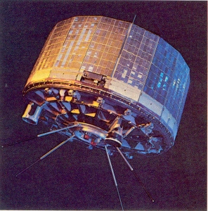
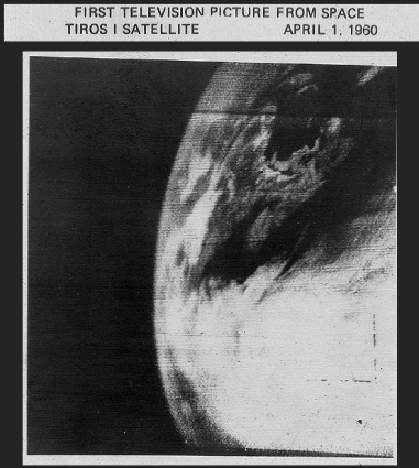
The
Television and Infrared Observation Satellite (TIROS) carried special
television cameras that viewed Earth's cloud cover from a 450 mile
orbit. By 1965, nine more TIROS satellites were launched. They had
progressively longer operational times, carried infrared radiometers
to study Earth's heat distribution, and several were placed in polar
orbits to increase coverage over the first TIROS in its near-equatorial
"polar" orbit...
History ...
in Czech republic
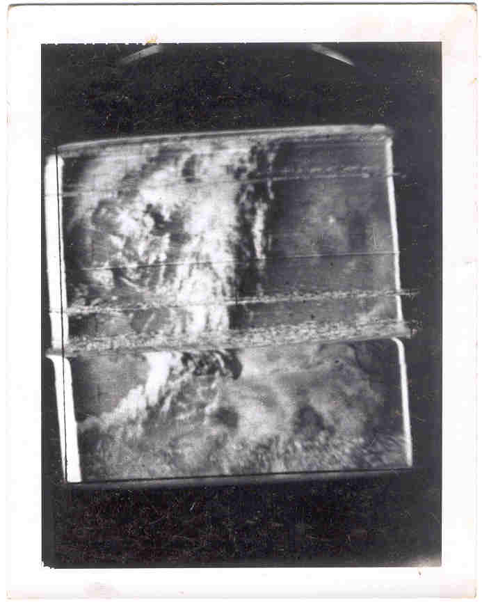
History ... Polar 1972 ( OK1BI photo front - back )
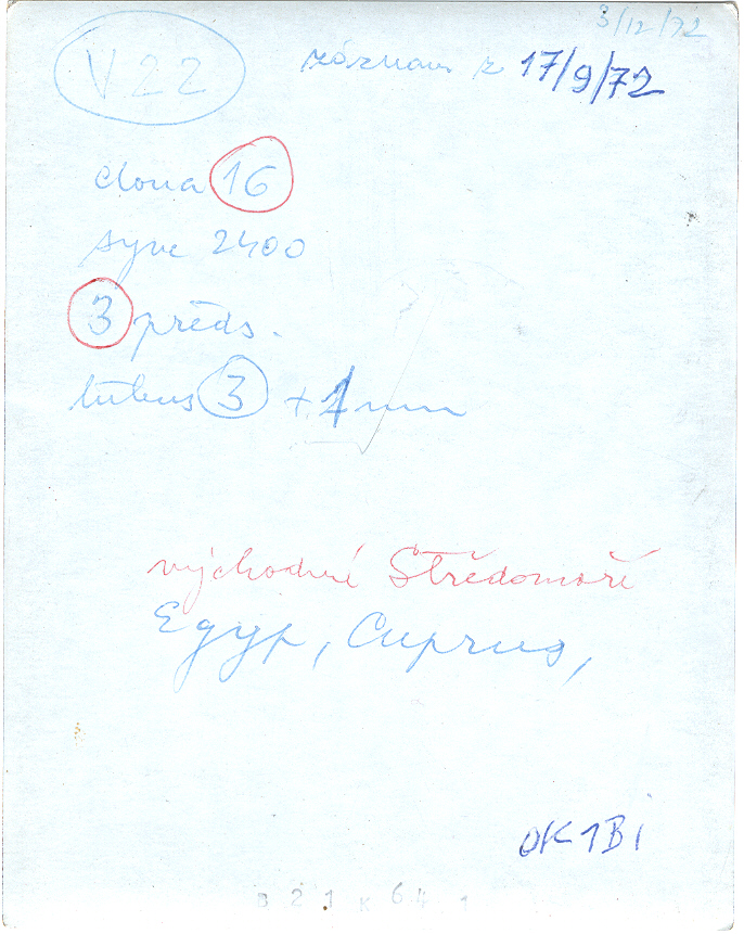
Images
were not generated using high quality decoding programs for personal
computers, simply because they did not exist at that time.
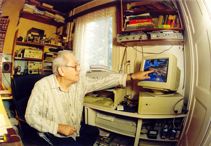
OK1BI HamShack 2001
The images were "decoded" using of technology of the seventies;
plotting on oscilloscope with medium afterglow and then photographing
using an instant Polaroid camera [9].
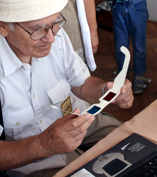
OK1BI
& WXtoIMG ...
stereoscopic study picture NOAA - 27. 08.
2005
Looking
at earth from space...
Satellites
NOAA POES ( NOAA POES (National Oceanic and Atmospheric
Administration Polar Operational Environmental Satellites, USA ) and
METEOR, OKEAN, RESURS (Russia) are the focus in this article. They are
flying on polar orbits around the Earth at the distance of
approximately 800 - 1200 kilometres passing over the same place at
approximately same time every day [23]. Satellites pass the North or
South pole on each orbit, that is why their orbits are called polar.
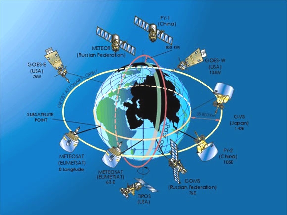
Satellite constellations [
movie_1
&
movie_2 wav_1 ]
It is
possible to determine their trajectory precisely using "Keplerian
elements", which describe the current orbit of the given satellite.
Calculation of the exact time of a satellites orbit, from the moment
when it appears at the horizon till the moment when it disappears
behind the horizon, can be made nowadays using many programs for
personal computers. I most frequently use a simple Windows program
called SatWin [10, 24]. A version of SatWin was also written for
MS-DOS and can be run on older personal computers of the DX486 type.
Both these programs can be downloaded free of charge together with up-to-date
Keplerian elements at the following address:
http://www.emgo.cz/ . You will
also find other information about the activities of satellites plus
the signals that you can receive and decode using the receiver
described in the following article.

Pictures are transmitted continuously from polar satellites without
beginning or ending.
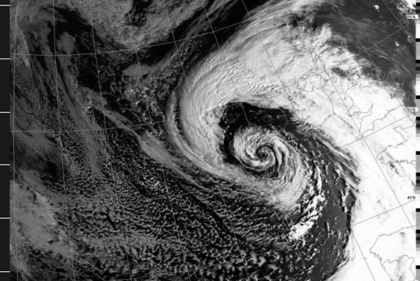
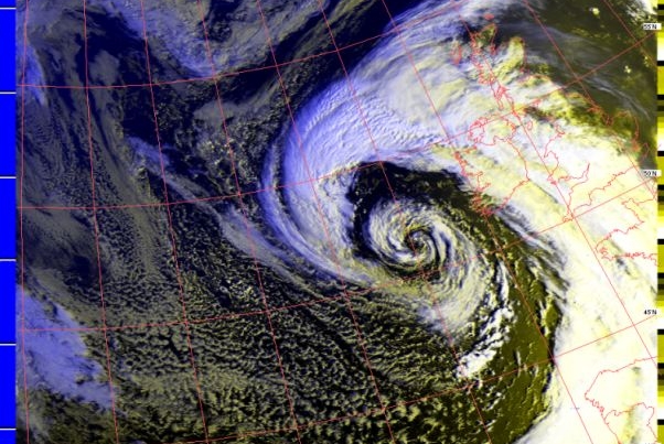
When the
satellite appears over the horizon, the edge of the pictures is
slightly cramped, gradually resolution of details in the picture
improves. At the end of orbit the signal gets weaker and the picture
begins to disappear in noise as the satellite slips behind the skyline.
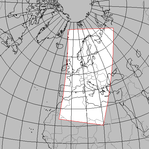
Inclination is the angle made by the plane of satellites orbit and
equatorial plane. A satellite that passes over both poles (on so
called polar orbit) has the inclination of 90°. The inclination of
American satellites NOAA 10-18 is 98°, their period is approximately
102 minutes and height of satellite is approximately 820 -850
kilometres.
Signals from the satellites are in WEFAX - APT format (Weather
Faximile - Automatic Picture Transmission). This is an old, but still
useful, system for transmission of black and white visual information
using a standard audio channel where a change of amplitude of the
2400Hz sub carrier represents the level of the video signal brightness.
Maximum modulation (black) is not zero, but approximately 5%, white is
then approximately 87%. This audio signal is frequency modulated on
the main carrier, e.g. 137.50MHz for the satellite NOAA 15.
APT is an analogue format: information is transmitted by means of AM/FM
modulation of the carrier frequency in 137 MHz radio wave band with a
bandwidth of about 40 KHz. Transmitted in the APT format are data of
only two channels, with lowered spatial (to 3.5 km) and radiometric
(to 8 bits) resolution.
After demodulation by the FM receiver we therefore obtain an amplitude
modulated tone of 2400Hz. This signal is sent to the input of standard
sound card in a PC and processed by a software decoder such as
JVComm32 which can be downloaded from
http://www.jvcomm.de/ . JVComm32 even handles bad quality
demodulated signals due to the efficient digital filters.
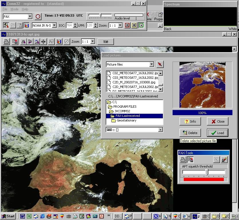
The
result of this processing is shown in Fig as picture displayed on a
computer monitor.

APT (Automatic Picture Transmission) format
Transmission of
images from NOAA satellites are composed of lines
lasting 0.5 second, which correspond with data from sensors. They
provide one picture of the Earth surface containing data from two
channels. Channel A transmits picture in the visible spectrum (VIS)
and channel B transmits picture in the infrared spectrum (IR). Each
line contains time multiplexed data from both channels and is composed
of separation tones interlaced with picture modulation. Data from
channel A is preceded by and short impulse of 1040Hz and similarly
data from channel B are preceded by and short impulse of 832Hz. Each
line also contains a calibration sequence. Thanks to this the decoding
program can display only the chosen type of picture. You will find
more detailed information at
http://www.noaa.gov/ .
You will find up-to-date information about
Russian satellites METEOR, OKEAN, RESURS at
http://sputnik.infospace.ru/
. These satellites have higher orbit than that of NOAA satellites
(1200 km). For example inclination of satellites METEOR is 82° and
their period is 115 min. The system of picture transmission from
METEOR satellites is compatible, however slightly different, from that
of NOAA satellites. Modulation is similar, but pictures contain only
one photo with higher resolution. Edges of lines contain sets of
phasing lines (alternately black and white), the lines mark end of
picture and greyscale. Pictures in the infrared spectrum do not
contain the greyscale. The pictures are also inverted as in comparison
with NOAA pictures. Photos from NOAA satellites show warmer places by
darker shade and colder places are brighter. The pictures from METEOR
use inverse scale warm seas are white and cold cloud formations are
black.
Summary of Russian Meteorological METEOR Satellites
Meteor 2-21
This is the last of the second generation Meteor satellite series.
This and similar satellites are in a non sun-synchronous orbit, so the
visible channel imagery is useful for only a portion of the year.
This spacecraft transmits on the
137.850 MHz channel with normal 120 line per minute visible mode APT.
It can alternately transmit on 137.400 MHz. It continues to show very
decreased signal strength during the approaching part of each orbital
pass. This would be consistent with a improperly deployed VHF antenna
or perhaps some damage to the antenna during launch. The second part
of each pass (as the spacecraft passes away from the observer) has a
much stronger signal, but is still weaker when compared to Meteor 3-5
or any of the NOAA series spacecraft.
Currently the spacecraft is in an
orbital plane with early morning and mid to late afternoon passes.
Meteor 3-5
This satellite, launched in 1991, is in a slightly higher orbit than
Meteor 2-21. It transmits on 137.300 MHz. Mechanically, it is similar
to Meteor 2-21. Which satellite is in operation depends on the sun
angles and consequently the seasons. Meteor 3-5 is usually the (Northern
Hemisphere) "summer" satellite while 2-21 is in operation for
approximately the half-year centered on winter.
Information about the APT
operating schedule and frequencies of the Meteor 2-21 and 3-5
satellites can usually be found on postings to the WXSAT-L list. See
our
links page
for more information about subscribing to WXSAT-L.
The Meteor-3M series of satellites
is to be an advanced series of polar orbiters with one 1.4 km
resolution visible channel and a ten-channel radiometer with 3 km
resolution. An APT transmission was planned to only have a reduced
resolution (2 km) visible channel data. The first of these, Meteor
3M-N1, was launched in December 2001. The status of any APT capability
on this satellite is unclear, but it is thought not to have an APT
transmitter. No APT transmissions have been received from this
satellite.
Russia also launched the RESURS 01-4
satellite in July 1998. This satellite carries a meteorological
package similar to what was planned for the 3M series, and may be a
cost saving effort to have these capabilities without launching a
separate satellite. APT-like transmissions from RESURS have been heard
on 137.40 MHz.
OKEAN 4 and SICH 1 are radar imaging
satellites that have been monitored as they dump recorded image data.
Both satellites have a transmission frequency of 137.400 MHz.
Reception has usually only been within Europe.
More information about these
satellites can be found at the
"Sputnik" site
in Russia. (You will leave the NOAASIS web site and NOAA domain when
following this link)
Have a
look at active in-reference: 
Weather
Satellite Images
recorded at Tenerife,
Canary Islands, Spain (on-line www) ...
It is also possible to decode visual information from the receiver any
time. To do this it is necessary to save the received modulated signal
as a WAV sound file on a high quality recorder (we had the best
results with SONY Minidisk). If you take holidays in distant countries,
it is recommended that you use a portable and easily mounted
Quadrifillar Helix antenna, take the receiver described below and a
Minidisk. During your trip you can record exotic pictures from any of
the meteorological satellites. When you return you can decode the
saved WAV sound files in the same manner as during direct reception
Description of the receiver RX-134(7)-141MHz
The RX137141MHz receiver has already been
produced since 1998 and I have been gradually implementing various
improvements of its technical parameters. The most recent modification
of the service properties of the receiver consists in a possibility to
connect it to a PC via the RS232 interface. This modification was
initiated by the interest of the WXtoIMG decoding program
http://www.wxtoimg.com/hardware/ users. The WXtoIMG
program has outstanding properties for decoding of the APT signals and
it enables a completely automated operation and optionally also an
automatic sending of the decoded image to the chosen web page. The WXtoIMG program
sends a special code
into the RX134141MHz
receiver shortly before the rise of the satellite to the horizon,
which will trigger the setting of the RX134141MHz
receiver to one of the following
ten
frequencies (
137.20 ..
137.10
.. 137.40 .. 137.50
.. 137.62 .. 137.9125
.. 137.30 .. 137.70
.. 137.80 ..
137.85 MHz
). The process is
continuously repeated before each flyover of the satellite in the
cycle, which is updated from the database of the current Keplerian
elements. The selection of the frequency for the given satellite is
substantially more reliable at present than it was in older models of
this receiver, with the use of SQL SCAN or PLL 2400 Hz SCAN with the
LM567circuit. The impact of interfering signals on the receiver’s
input that afterwards caused a process of undesired repeated scanning
never occurs now.
At present I have
started the production of a new model of the RX134141MHz receiver with
an extended range that was inspired by the needs of users of the
converter 1700MHz made in
Italy,
the output frequencies of which are 134.00 a 137.50 MHz. The new model
of the receiver embodies all good properties, which were confirmed
during a six-year-long practical use by numerous users in many
countries.
The
receiver RX-134(7)-141 MHz is designed to receive images of the Earth
surface from polar-orbiting satellites in APT (Automatic Picture
Transmission) format in 137 MHz band. The receiver RX-134(7)-141 MHz
has been designed for high quality reception of signals form polar
meteosatellites NOAA, METEOR, OKEAN and others. It is compatible with
the converter from 1691.00 MHz to 137.50MHz which is suitable for
reception from geostationary satellite METEOSAT 7.
Table: Satellite Status Information ( NOAA Operational Satellites )
| Satellite |
Transmission Frequencies |
| NOAA-19 |
APT - ON
137.10 MHZ |
HRPT - 1698
MHz |
| NOAA-18 |
APT - ON
137.91 MHZ |
HRPT - 1698
MHz |
| NOAA-17 |
APT - ON
137.62 MHz |
HRPT -
1707.0 MHz |
| NOAA-16 |
APT - OFF
since 11/15/00 |
HRPT -
1702.5 MHz |
| NOAA-15 |
APT - ON
137.50 MHz |
HRPT -
1702.5 MHz |
| NOAA-14 |
APT - OFF
since 8/2/05 |
HRPT -
1707.0 MHz |
| NOAA-12 |
WEFAX/LRIT -
1691.0 MHz |
HRPT -
1698.0 MHz |
Satellite Transmission Frequencies Notes
Not all the satellites given are always active. Some of them are still
flying on polar orbits, but their transmitters have been switched off.
Some others do not transmit due to a failure, e.g. the modern
satellite NOAA 16 only transmits in the mode HRPT at the frequency
1.698 GHz due to a defect. This is the fate of all artificial
satellites, when they fail they can only be repaired using very costly
methods. Not all the satellites are as important as the Hubble space
telescope, which was repaired by the space shuttle that we watched
with excitement and admiration. See
http://noaasis.noaa.gov/NOAASIS/ml/status.html
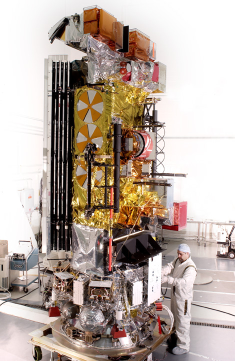 
NOAA-N (NOAA-18) Rockets Into Orbit...
Looking at the Table 1, you will find that satellites in polar orbits
transmit signals in the range of 137.10-137.62MHz, therefore a very
narrow frequency range is sufficient. We have chosen, for practical
reasons, a lower frequency of 134.00MHz and an upper frequency of
141MHz. No meteorological satellites transmit at frequencies above
137.85MHz but the frequency of 141MHz will make it possible to use the
converter for the METEOSAT 7 satellite. This makes it possible to
process information from both channels, the first channel (1691.00MHz)
converts to 137.50MHz and the second channel (1694.50MHz) converts to
141.00MHz.
Since the design of the RX134141MHZ receiver will only
accept frequency steps of 10 KHz, the new 137.10 frequency (NOAA-18)
cannot be exactly programmed, so I chose the closest values above and
below that frequency. The error is only 2.5 KHz, so either channel
should be able to receive the APT signal with minimum degredation. Due
to doppler shift, the recption may be slightly better on one channel
while the satellite is approaching, and it may be better on the other
channel as the satellite moves away from your location.
The circuit diagram of the
receiver is shown in Fig 1. It was originally developed for the
nearby ham frequency range of 144-146MHz [3]. The circuit of the
receiver is designed for wideband FM (bandwidth 30kHz). The low-frequency
APT/WEEFAX signal is sent from the output to the PC sound card. The
frequency synthesiser PLL and LCD display are controlled by an ATMEL
micro-computer ( UP-MODE-DOWN ).
The receiver is a double conversion superhetrodyne. Design of the
receiver has been significantly simplified by using an
MC3362P (IC1) integrated circuit made by
Motorola [5], which comprises all main elements of modern FM receiver.
All that is required to connect to the MC3362P is an input band-pass
filter, a resonant circuit for the first mixer oscillator, 2 ceramic
filters for 10.7MHz and 455kHz, a quartz crystal oscillator for the
second mixer, a resonant circuit for the demodulator and few other
passive components. We will thus obtain an excellent receiver with a
rather simple circuit and with supply voltage of 2-5V [12].
Table: Specification of the receiver.
|
|
Frequency
Range : |
134 - 141 MHz
(infinitely adjustable, step by step 10 kHz) |
|
Frequency
Synthesizer Step: |
10,0 kHz |
|
Input
Sensitivity: |
0,25uV (rms-type)
for 12dB SINAD |
|
Intermediate
Frequency: |
10,7 MHz and 455
kHz |
|
Tone decoder/PLL
SE567: |
2400 Hz |
|
Pass band of the
2-st.IF filter: |
30 kHz/ - 3 dB
(or
alternately 15 kHz) |
|
Power: |
DC 12V
(max.12 V) |
|
Current output: |
70 - 90 mA,
according
to the loudness level setting |
|
Power Connector: |
3 mm (+pole
is inside of the jack pin,-pole is on its surface!!!) |
|
WXtoIMG Scanning
|
Yes
/ 10 -channel, controlled by the uP [ RS232 or USB ] |
|
Automatic
Scanning: |
Yes - 2400 Hz
stop point - Squelch function controlled by the uP |
|
Noise
Gate ( SQUELCH ): |
Yes |
|
Antenna
Connector: |
2x "BNC" or
SO239 type |
|
Display: |
LCD
1 x 16 alpha - numerical
symbols |
|
Connection for
Loud
speaker: |
(or
Headphones) external 8-25 Ohms, CINCH connectors |
|
Connection
for PC1: |
2PIN connectorsor
cable from the computer sound card |
|
Connection
for PC2: |
9PIN connectorsor
cable from the computer COM/RS232 card |
|
Receiver
Size: |
Case Bopla: 225x200x70 mm |
|
|
Antenna
A requirement for
assuring high quality reception of signals from meteorological
satellites is the use of a high quality
antenna. Polar meteorological satellites are rotation
stabilised and transmit circular polarisation. It is therefore
impossible to use ordinary Yagi or ground plane antenna. When you
listen to the signal from the loudspeaker it seems to be noise free,
however when you observe the picture after it is decoded you will see
that it is unusable. Anyone can build high quality antenna. Two basic
types are used: Turnstile and Quadrifillar Helix.
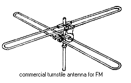
General view of a Turnstile antenna.
The turnstile consists
of two crossed dipoles (Fig. 2) phased for circular polarisation. This
antenna should be situated as high as possible above the horizon,
preferably above the house roof or in an open air space. Experiments
made with a turnstile antenna located on the
balcony of a blockhouse, satellites flying over at a low
elevation angle were shielded by building or balcony. In short, it is
only possible to receive signals that are "seen" by the antenna.
Instructions for building
several types of turnstile antennas are on the authors homepage.
Drawings describing the construction of
a simple antenna made from plastic tube and 8 - 12 mm aluminium
tube are given in the literature [18].
We have
tested the antenna shown in Fig 3 with the receiver. The antenna was
installed on a roof at 40m above the ground and gives high quality
signal reception. The feeder connection for circular
polarisation is shown in Fig 4. Fig 5 shows the polar diagram
for this antenna, particular attention should be paid
to the dipole to refelctor spacing because it changes the polar
diagram, the author chose 3/8 lambda.
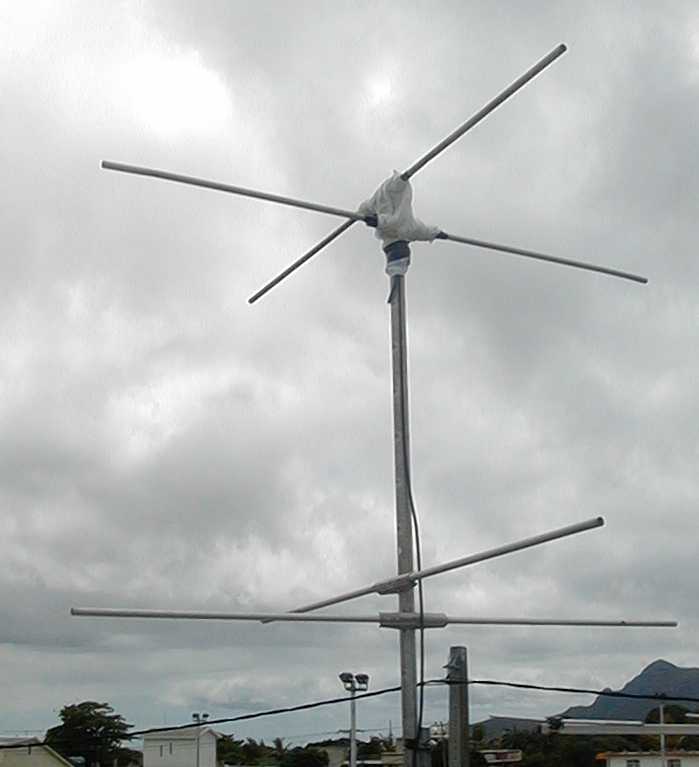

Practical design of a turnstile antenna.

Details of feeder for turnstile antenna.
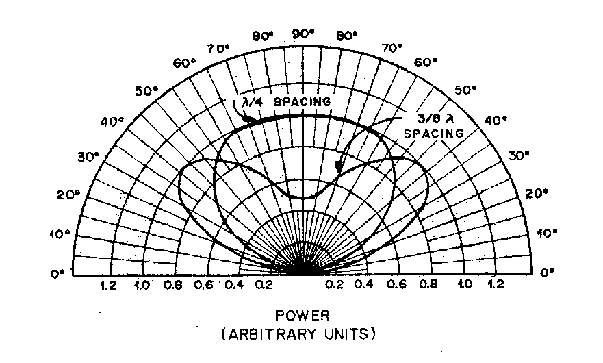
Polar diagram for turnstile
antenna
The manufacture of the
Quadrifillar Helix antenna, which is shown in Fig. 6 can be done only
in a well equipped machine
shop.


General views of
Quadrifillar Helix antennas. QFHA KIT EMGO
and Russia version
This antenna has
slightly better reception of signals and moreover it can be used also
in moving objects, such as
yachts cruising in Mediterranean Sea.The article [20, 21] contain many
descriptions of simpler mechanical constructions
suitable, however, only for a shortterm seasonal use, or for
antennas made of copper heating tubes.
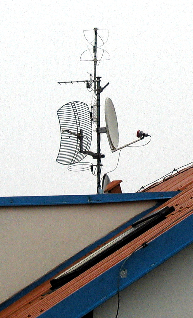
If the distance of your
receiver from the antenna will exceed 10m, I would recommend use of
selective preamplifier for frequency range of 137MHz, preferably using
bipolar transistor. Experience has shown that summer storms have a
rather bad impact on MOS-FET transistors. In an environment with
industrial interference it is often desirable to use a band pass helix
filter in front of the preamplifier.
|
|
Power supply for the receiver
The receiver requires a
stabilised power supply adapter with a voltage of 9 - 12V. It is
highly that you pay special attention to the selection of a power
supply adapter.


If you have an
oscilloscope, look at it's output when on load at 150mA and check that
there is no ripple. The low-frequency
amplifiers IC2 and IC6 are fed directly from the adapter. The
other supply voltages, 5V for receivers circuits and 5V for
synthesiser and microprocessor, are stabilised by IC5 (LM7805).
The supply voltage for the analogue part of
the receiver is also isolated by choke TL2.

The input of the power
supply is protected against reverse polarity by diode
D2. Bridging jumper JP2 enables the use the feeder cable to
supply the antenna preamplifier or Meteosat converter. This requires a
higher capacity power supply adapter, for connection of the OK2XDX
Meteosat converter [16], I recommend a power supply adapter of
12V/500mA.
Description of software WXtoIMG
Source: WXtoIMG
http://www.wxtoimg.com
- setting
WXtiOMG Version
wxinst21010
Basic set-up for communication with the
Interface EMGO RX134141MHZ/WXtoIMG/RS232
 ( UP-MODE-DOWN )
Communication with PC –
setting of frequency of received signal
Quality reception of signals from NOAA satellites requires mutual
collaboration of all the hardware and software components – preferably
without any human intervention. That’s why the receiver’s features
were extended by adding an RS232 communication channel, which is
designed to work with an outstanding decoding program, WXtoIMG.
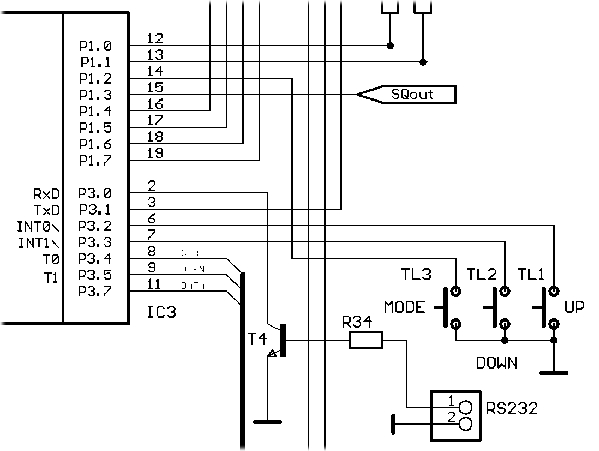
Condition: The program WXtoIMG must have the valid (most current) set
of Keplerian data (e.g. NORAD Two-Line Element Sets Current Data). At
the moment when satellite appears on the horizon, the program WXtoIMG
sends a code to the receiver, which will tune its frequency within the
137MHz band. The receiver then transmits a 2400Hz modulated signal to
the computer (via the sound card), which is then transformed into an
image by the WXtoIMG program. When the satellite disappears behind the
horizon, the receiver and computer are switched into a standby mode
and await the next code generated by the program WXtoIMG at the
moment, when next satellite appears on the horizon.
The
current code transmitted into the receiver will tune it to another
frequency within the 137MHz band. This new function of the receiver
enables fully automatic unattended reception of images and storing
them on computer’s hard disk or directly to the relevant web page.
Inter-connection of receiver and computer is unidirectional (from PC
to the receiver).

PIN 3
of the connector COM1 on PC is connected with the PIN_RS232 (the first
conductor – e.g. a low-frequency cable) and PIN 5 of the connector
COM1 on PC is connected with the GND of the receiver (the second
conductor, preferably formed by shielding (braiding) of the low-frequency
cable).
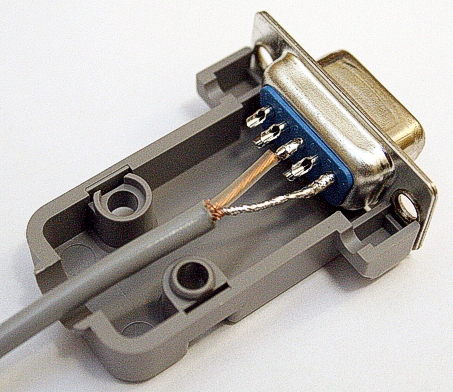
It is also possible to use a standard COM9PIN cable without
crossover of the conductors RX and TX for this connection.
Testing program :
RX134141MHZ/RS232/WXtoIMG CODE (ZIP file)
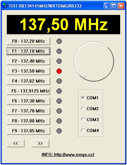
Configuration of the
program WXtoIMG for reception of satellites NOAA or METEOSAT
is very simple (www support
- help) . Set the mode to NOAA or METEOR, and the Interface type to
Sound Card. The help


 with this program
is also very user friendly, you will find all the details of setting
and operation.
1. WXtoIMG:
Options/Ground Station Locatinon
2. WXtoIMG:
Options/Recording Options
2a. WXtoIMG:
Options/Recording Options (alternate)
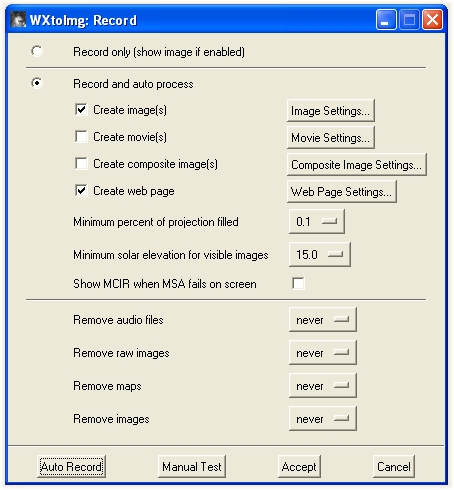
3. WXtoIMG: File/Record
4. WXtoIMG: Options/Map
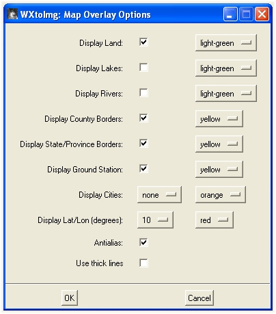
Overlay Options
Basic set-up for
communication with the Interface EMGO RX134141MHZ/WXtoIMG/RS232 (
http://www.emgo.cz/
)
Program WXtoIMG has many
functions, thanks to which it is a very powerful tool for reception
and decoding of images from meteorological satellites. You can run the
program in basic mode as freeware without necessity to pay any licence
fee. Should you wish to use its extensive more complex functions, you
can choose one of several licences for accessing full version of the
program.

...
two-colour glasses for
stereoscopic study picture NOAA (part of
licence WXTOIMG SW)
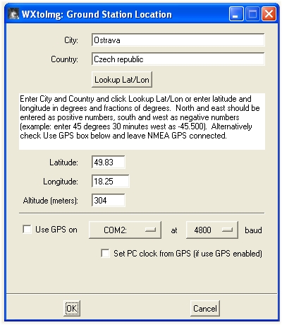
1. Set the exact QTH coordinates
(geographical). Option-Ground station location1.
Set the exact QTH coordinates (geographical). Option-Ground station
location.
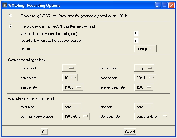
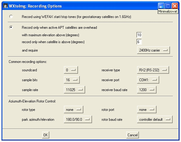
2. Setting of options in the system of
reception of images and communication
port for RX134141MHZ/WXTOIMG/RS232. “Option-Recording options”.
3. Set the type of satellite
in the menu “Satellite” to “Autodetect”.
4. Set the satellite approach direction
in the menu “Direction” to “Autodetect”.
5. Start recording
of received images. “File-Record”.
If you do not want store the pictures on the web, do not check the
item “Create web page”. By clicking the “Image Settings” you will set
the spectre, in which you want the final pictures generated. After
clicking the “Record” the program will be switched to the mode of
waiting for approach of the satellite.
6. The received image
can be either OK or it may consist only of more or less angled lines.
If you see instead of the image just some skew lines, set the option
“Options-Disable PLL”, afterwards choose the “Image-Slant correction”
and draw by mouse a straight line over this skew line. Computer will
re-calculate the „sampling“ frequency. In the “Options-Disable PLL”
uncheck the option and everything should be now OK.
7. You can set outlining of contours of
countries, rivers and towns in the final
picture. Use the menu “Options-Map Overlay Options” to enable this
feature.
8. If you do want to remove telemetric
data from the images (vertical lines at
the image sides), you can switch-off this option in the menu item
“Options-Crop telemetry”.
Important final notice: It is absolutely necessary to update regularly
Keplerian data (
http://www.celestrak.com/NORAD/elements/weather.txt
), otherwise contours of countries can be shifted when the map is
inserted into the images. I do it myself on a daily basis.
Shall reply here:
emgo@vuhz.cz
 http://www.emgo.cz/
|
|
[
BACK
]
Literature
[1 ] Günter Borchert
DF5FC, Funkamateur 2/1995, str.
153 - 156 Der Wetterfrosch -
ein 137 MHz
Satellitenempfänger, continuation in Funkamateur 3/1995, p. 274
[2] Ing. Radek Vaclavik OK2XDX,
Prijimac a interfejs WXSAT (prijem snimku z orbitalnich meteosatelitu)
[Receiver and interface WXSAT (receipt of images from orbital
meteorological satellites)]. A-Radio Praktická elektronika, series of
articles in issues Nos. 2-6/1997.
[3] OK2UGS.: Prijimace
FM v pasmu 144 - 146 MHz s obvodem Motorola
MC3362 [FM receiver for the band 144 -146
MHz with the circuit Motorola
MC3362]. A_Radio_Electus-99, pp.73-79
[4] Marsik, V.:
Kmitoctova synteza oscilatoroveho kmitoctu rozhlasovych prijímacu [Frequency
synthesis of oscillator
frequency of radio receivers], Amaterske
Radio B3/1987, p. 88.
[5] Motorola, Linear/Interface
ICs Device Data, Vol.II, str. 8-82
[6] Philips
Semiconductors, SAA1057 -Radio tuning PLL frequency synthesiser,
November 1983.
[7] ATMEL, AT89C2051
8.bit Microcontroller with
1kbyte Flash, catalogue sheets
August 1994.
[8]
DF2FQ: VHF Empfanger, CQ DL
1/1994
[9] Borovicka, Jiri,
OK1BI. Personal consultation history of receipts from the Meteosat,
Antenna Turnstile
[10] Our location
database includes most towns
and villages in the entire world (over 2 million places!)
http://www.heavens-above.com
/
[11] OZ1HEJ, Pedersen,
Michael: Receiver with LCD readout:
http://ozon.homepage.dk/eng/elcd.htm
[12] OK2UGS.: Prijimace
FM v pasmu 144 - 146 MHz s obvodem Motorola
MC3362 [FM receiver for the band 44 -146
MHz with the circuit Motorola
MC3362]. Elektroinzert 5/97 p. 6.
[13] Philips
Semiconductors: SE567-Tone decoder/phase-locked loop, , 4/92
[14] OK2UGS.:
http://www.emgo.cz
[15] Ing. Radek Václavik,
OK2XDX: Prakticka elektronika No. 7/1999 construction guide to
building of converter LNC1700 MHz
[16] L. B. Cebik, W4RNL:
http://www.cebik.com/turns.html The Turnstile An Omni-Directional
Horizontally Polarized Antenna
[17] Martin DH7GL:
http://www.emgola.cz
[18] Ruud JANSEN'S
PA0ROJ: QFHA
http://www.hshaarlem.nl/~ruud/ Skladaci antena na cesty za
poznanim [Foldaway antenna for exploration trips]
[19] Steve Blackmore:
QFHA
http://www.pilotltd.net/qha.htm
(step-by-step construction
guide to building and QHFA)
[20] Borre Ludvigsen:
http://abdallah.hiof.no/~borrel/QFH/ QFHA - More pictures and
construction picture above is one of the designs on this site.
[21] Josef Danes et al:
Amaterska radiotechnika a elektrotechnika, 3. cast , Mereni na
prijimacich [Ham radio and electrical engineering, 3rd part,
Measurement on receivers], pp. 190
254, Nase vojsko, Praha 1988.
[22] Kucirek, Petr:
Program SatWin predpovidi doby
preletu satelitu nad zvolenym
uzemim [Program SatWin prediction of time of passages of satellites
over the selected territory]
[23] Eberhard Backeshoff,
DK8JV e-mail address:
Feedback@jvcomm.de , homepage:
http://www.jvcomm.de/
[24]
WXtoIMG
is a fully automated APT and WEFAX weather satellite (wxsat) decoder
[25] Vaclavik, R,
OK2XDX: Easy down-converter
for Meteosat, VHF Communication 4/1999, page 196 - 207.
http://www.vhfcomm.co.uk/
[26] Vaclavik, R,
OK2XDX: Small receiver for Meteosat, VHF Communication
4/1999, page 208 - 217.
http://www.vhfcomm.co.uk/
|
Copyright 2000 ,
2001, 2002, 2003, 2004, 2005, 2006,2007, 2008, 2009, 2010
emgo@vuhz.cz or
emgo@emgo.cz
|
|
|
|
|
|